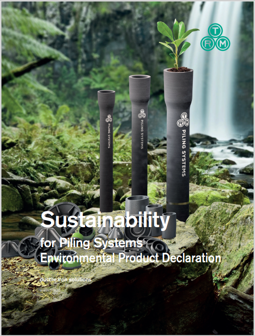
DUCTILE IRON PIPE PILE PRODUCTS
Ductile Iron Pipe Piles (DIPPs) are a simple, fast and highly effective modular, low-vibration driven pile system comprised of high-strength ductile cast iron. Pile sections are connected by a proprietary Plug & Drive joint system, eliminating the need for field welding and splicing while providing a high degree of stiffness and full moment capacity. With the use of an excavator fitted with a hydraulic hammer, piles are installed in quick succession leading to fast and easy installation.
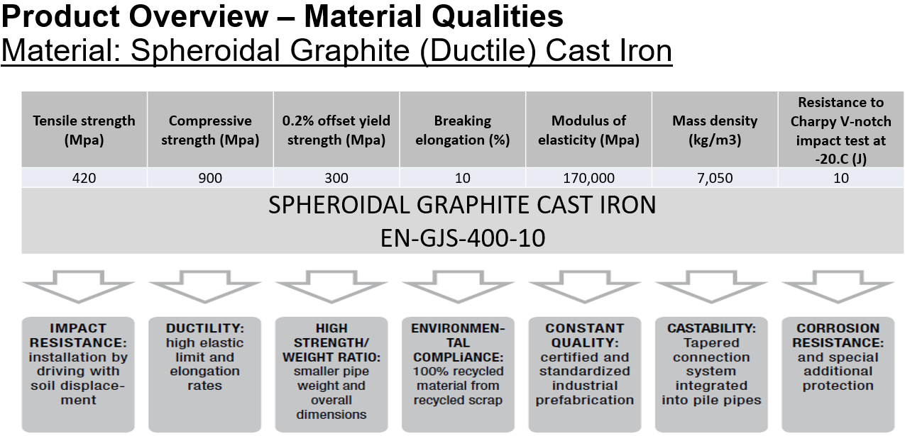
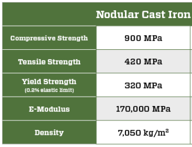
Ductile Iron Pipe Piles are manufactured by Tiroler Rohre, GmbH of Austria from ductile cast iron, which provides high-impact resistance to the low amplitude, high frequency installation energy. The material also exhibits high ultimate strength, elastic limit and ductility as well as superior corrosion resistance when compared with traditional steel piles.
Ductile Iron Pipe Piles are well-suited for supporting loads in a variety of problematic soil conditions including both cohesive and non-cohesive soils and can also resist compression and tension loads.
PILES & ACCESSORIES
END-BEARING & FRICTION PILES
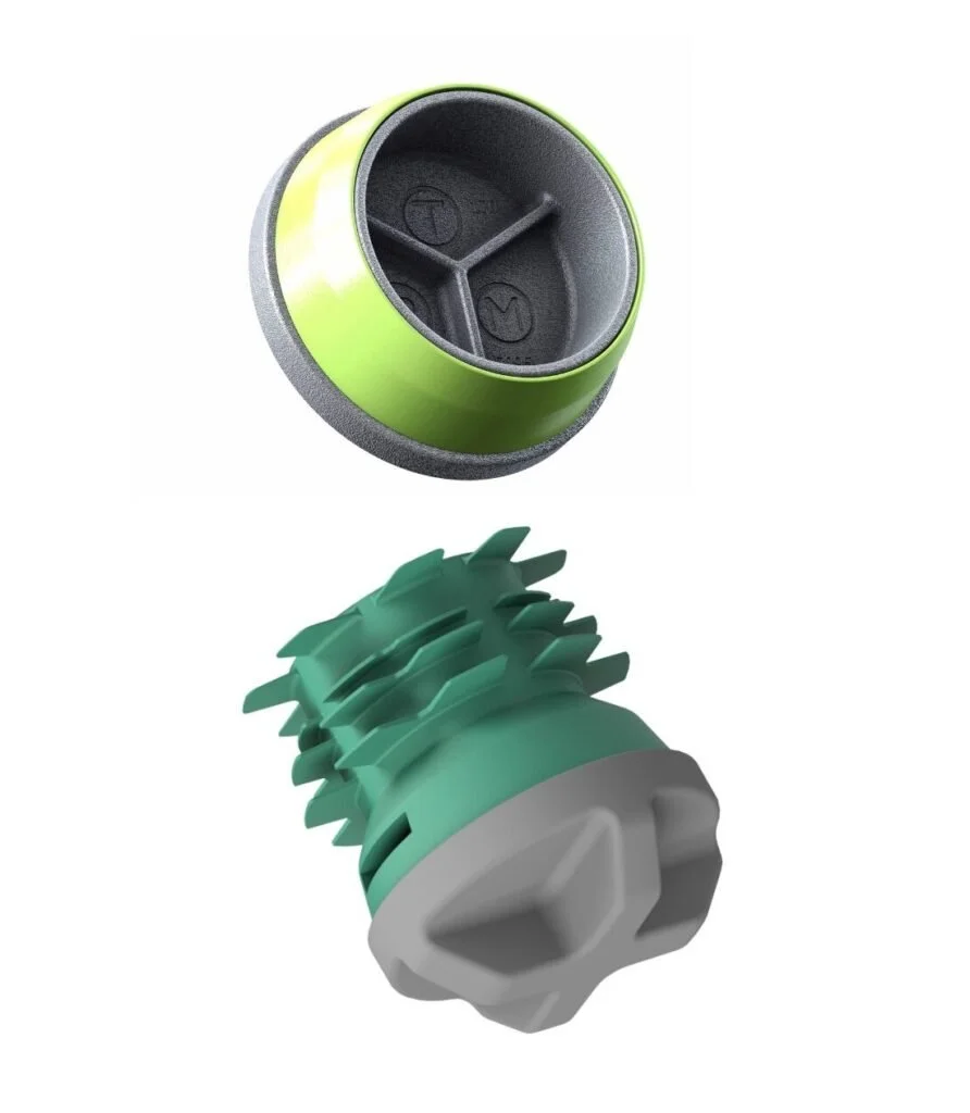
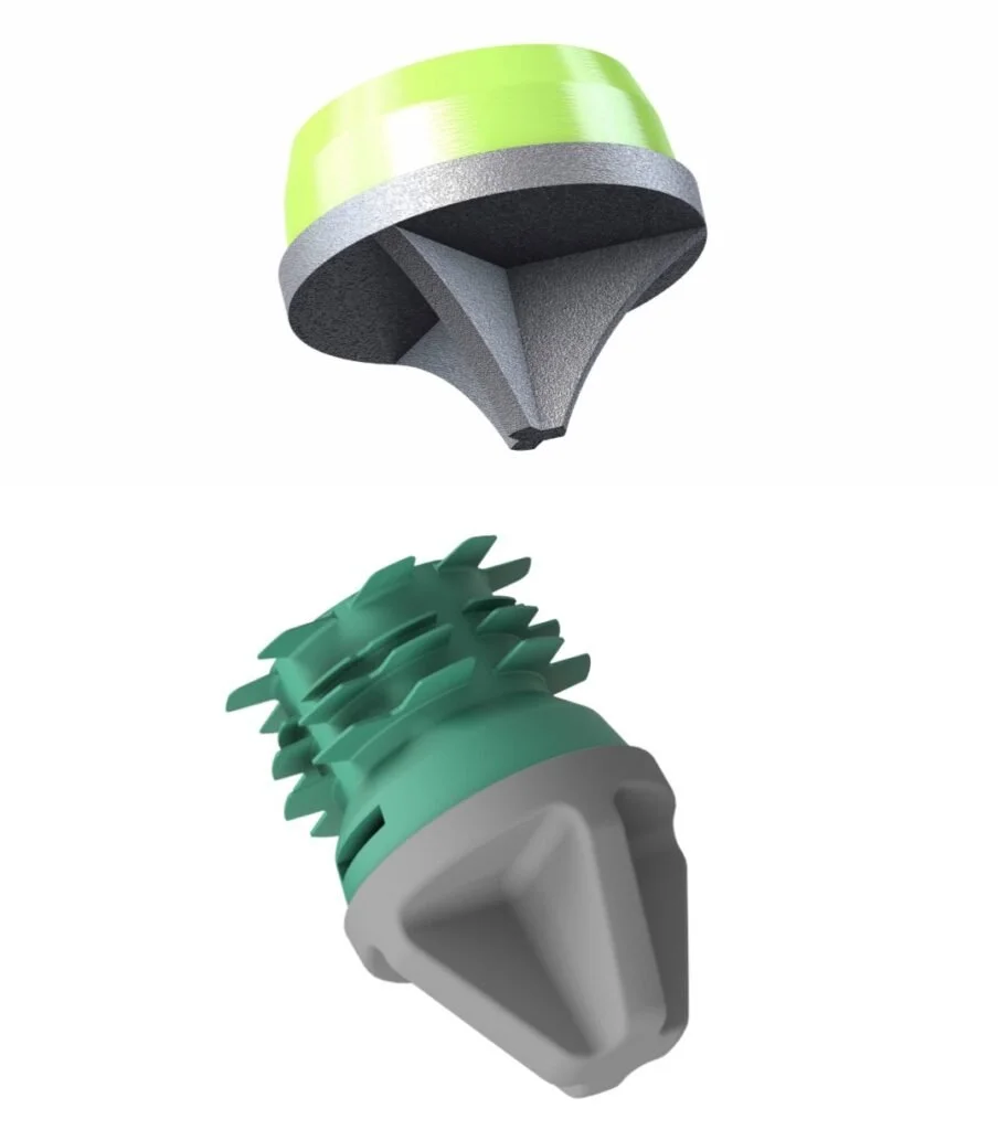
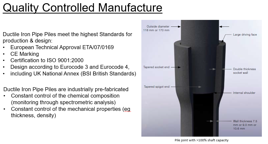
Ductile Iron Pipe Piles have been manufactured by Tiroler Rohre GmbH (TRM) in Austria for over 35 years. Each modular pile section features a Plug & Drive connection consisting of a tapered socket with an internal shoulder for full engagement at one end and a tapered spigot at the other end. This allows the individual pile sections to be connected together to form a pile shaft of virtually any length without the use of special tools. The connection is formed by elastic deformation of the ductile iron and by cold welding of the friction surfaces. This joint exhibits high-compressive strength and superior resistance to bending, such that the rotational stiffness of the joint is greater than the main pile shaft. This connection method eliminates the need for threads, couplers, pins and keys and field welding/splicing on the job site.
Ductile Iron Pipe Pile installation methods consist of either dry (no exterior grout) or wet (continuous grouting operation during installation) installations. Additionally, both options can develop load-carrying capacity in either friction in competent soils, end-bearing on very hard ground/rock or a combination of both. The specific pile materials and accessories depend on the type of installation and mechanism for load resistance. Both methods utilize a unique combination of installation speed and high capacity that results in a highly cost-effective deep foundation system.

End-Bearing Piles
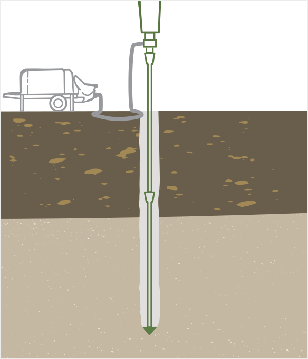
Ductile Iron Pipe Piles installed for end-bearing are driven through compressible and unsuitable soils to transfer their load to a hard stratum below. They derive most of their load-carrying capacity thru resistance along the portion of the shaft in competent soil and at the toe of the pile. End-bearing piles may be installed using a dry installation method without continuous grouting during installation (as pictured) or as the wet installation method with oversized pile shoes and continuous pumping of exterior grout.
Friction Piles
Ductile Iron Pipe Piles installed as friction piles penetrate poor soil conditions and develop the majority of the load-carrying capacity in frictional resistance along the perimeter of the pile shaft in the competent strata. While some friction piles use a dry installation method (without continuous grouting) and develop strength through the interface between the soil and the roughened exterior of the ductile iron pile shaft, the majority of friction piles utilize oversized conical drive shoes and exterior grout to encapsulate the pile during driving for very effective grout to ground bonding. The oversized cap results in significant expansion (and densification) of the competent soil while the grout-to-ground bonding provides a highly efficient mechanism for load transfer
DUCTILE IRON PIPE PILES MATERIAL SPECIFICATIONS
Ductile Iron Pipe Piles are typically manufactured in standard (usable) lengths of 5 meters.
Overall pile lengths including the bell (socket) are slightly longer and range from 5.15 meters to 5.25 meters.
Piles are available in multiple diameters and wall thicknesses to suit project needs.


The same pile sections are used for both end-bearing and friction applications. However, the various accessories are specific to the type of application and method for loading resistance:
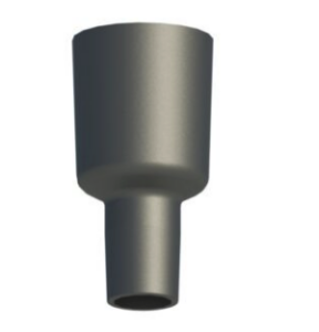
Flat End Drive Shoe
Standard drive shoes for piles installed using the dry installation method
Rock Point
Alternative drive shoes for dry installation methods, typically for end-bearing (non-friction) piles, used when driving through harder material such as partially weathered rock or glacial till.
Heavy-Duty (HD) Flat Drive Shoe
Heavy-duty (HD) flat drive shoes for dry piles are used when driving through hard conditions such debris fill, partially-weathered rock or glacial till for greater durability during driving. HD caps are also used in very soft soils to reduce the potential for dislodging of the drive shoe during driving.
Conical Grout Shoe
Conical grout shoes are used for installation of exterior grouted (wet installation) piles. Grout shoes have a larger diameter than the pile, creating an annulus around the pile which enables the placement of fine-aggregate concrete (grout) to encapsulate the full length of the pile shaft. Grout shoe diameters range from 150 mm (5.9 in) to 370 mm (14.6 in). Appropriate shoe sizes depends on the pile size, soil conditions, hammer size and desired design capacity.
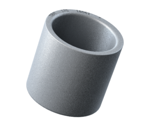
Coupler
A coupler is used to connect two partial pile sections in place of the standard spigot and socket connection. Couplers are most often used when piles are driven in low headroom environments where pile sections must be cut for overhead access. Couplers are not required for standard applications with full-length pile sections utilizing the Plug and Drive connections.
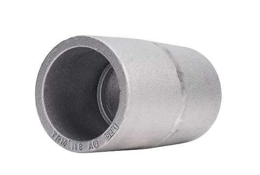
Converter
A Converter is used to switch from a Series 118 pile to a larger Series 170 pile. The Plug and Drive converter is installed into the bell of a Series 118 pile and a new Series 170 pile is then inserted and driven. The converter is often used for situations where a larger pile size is required at shallow depths to resist lateral loads, but the axial capacity does not require the larger pile for the full length.
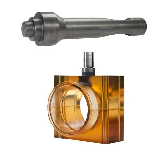
Drive Shanks and Grout Box
A drive shank is a specialized attachment that facilitates the driving of the piles using conventional hydraulic percussion (breaker) hammers. Drive shanks are specially fabricated and hardened to withstand the high driving stresses during installation. Drive shanks are available as 1) solid or dry shanks for installation of dry piles (ungrouted during driving) and 2) wet or grouting shanks to facilitate grout injection into the pile interior during installation of grouted piles. The grout box is designed to surround the wet shank and provide a grout reservoir during grouted pile installation. A wet shank and grout box are used in concert.
SAFETY
The construction industry needs safe simple piling systems that are fast to install and universally usable.
The Ductile Iron Pipe Piles are driven into the ground and effectively transmit the forces from the building or bridge structure into the load bearing strata in the ground.
The equipment used is light weight and mobile using excavators as the base machine to carry the high frequency percussive piling hammer.
The use of excavators rather than traditional fixed leader piling rigs with vertical masts allows smaller working platforms and access tracks which do not have to be engineered to the high standard required by the fixed leader rigs. The risk of rig overturning is substantially reduced.
The working platform and access are made suitable for a 20 - 40 ton excavator and 5m3 ready mix truck. As there is no fixed leader with drive motor / hammer at height causing high overturning loads the platform does not have to be engineered and certified. The excavator can cope with different levels in the platform if required.
The piles are supplied in 5m sections for easy and safe handling.
The short pile length reduces the fall radius and exclusion zones required.
The operators cab is normally outside the fall radius.
The spigot pile joint results in a positive joint with immediate capacity thus minimising any risk of the upper section falling.
The joint does not require completion by the site crew eliminating exposure of the crew to falling piles or hammers.
Only a small crew is required to install the Ductile Iron Pipe piles leading to a reduced exposure to any hazards on site.
The excavator boom allows the base machine to stand back from the pile being driven allowing piles to be driven downslope on embankments without the requirement for multiple working platforms or the rig accessing the slope.
ENVIRONMENTAL CONSIDERATIONS
DIPP piling is an environmentally friendly piling technique due to:
•Excellent corrosion resistance of ductile cast iron
•Piles made of 100% recycled materials
•No wastage as offcuts are re-used on the next pile
•No spoil handling or removal required
•Minimal disruption to environment due to use of comparatively lightweight compact equipment, reduced coverage of the worksite and limited platform preparation
•Minimal vibrations compared to standard piling techniques (<=2mm/sec)
•Ductile Iron Pipe Piles have been awarded an EDP (EnvironmentalProduct Declaration)
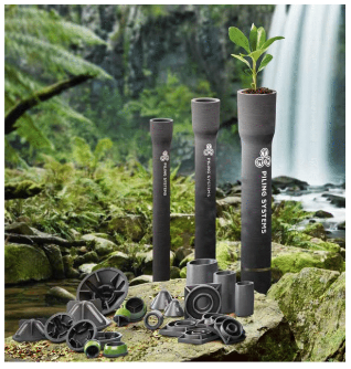
Product Overview - 100% Recycled
ACCESS TRM PRODUCT INFORMATION BROCHURE Here
ACCESS TRM ENVIRONMENTAL PRODUCT DECLARATION Here
DURABILITY
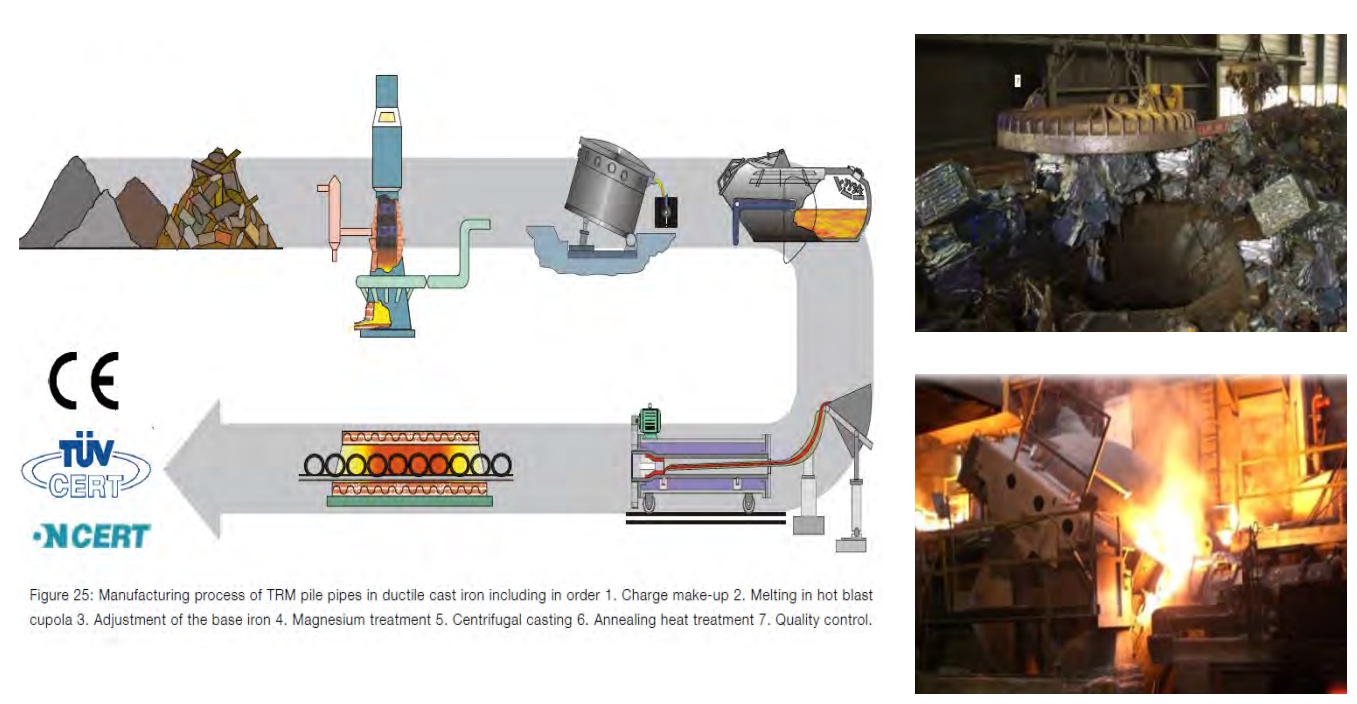
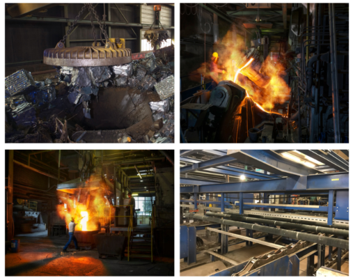
The manufacturing of TRM Ductile Iron Pipe Piles includes the following process:
Make-up of the charge
Melting the charge in hot blast cupola
Adjustment of the base iron content
Magnesium treatment
Centrifugal Casting
Annealing heat treatment
Quality Control
MANUFACTURING PROCESS - ADVANCED TECHNIQUES
Ductile Iron Pipe Piles are comprised of grey cast iron
This material has been used for commercial pipeline construction since early 1800
Historically cast iron or grey cast iron was produced in a lamellar form
The material was often brittle and exhibited low strength and impact resistance
Advancements over 50 years ago led to the development of spheroidal or ductile cast iron by adding magnesium to the cast iron before pouring
Magnesium produces crystallization of graphite in spheroidal form
The development of spheroidal graphite cast iron led to more desirable material properties:
Improved ultimate and yield strength
Improved tensile and flexural strength
Improved impact resistance for drivability and toughness
Maintained cast iron qualities including machinability and casting
During manufacturing of the Ductile Iron Pipe Piles, the ordinary grey or lamellar graphite undergoes a sophisticated manufacturing process that transforms it into spheroidal graphite or ductile cast iron. This process drastically improves the cast iron’s impact resistance, ductility, tensile strength and flexural stiffness.
The ductile cast iron material used in the piles contains a high recycled content and is comprised of: 90-95% scrap metal iron, approximately 3.7% carbon, and approximately 2.7% silicon.
Ductile Iron Pipe Piles are manufactured by Tiroler Rohre GmbH (TRM) in Austria. Ductile cast iron used in the fabrication of the piles undergoes a sophisticated centrifugal- or spun-casting manufacturing process to transform the raw recycled material into the finished product. The ductile iron pipe piles are factory prefabricated to precise tolerances. Standardization results in the materials being subject to strict control of its chemical composition and its mechanical properties throughout the fabrication process.
Click here to view the manufacturer brochure
The manufacturing process employs a quality assurance system that is certified in compliance with ISO 9001:2000 “Quality Management Systems”. Further, a variety of other European inspections and certifications are deployed at key stages throughout the manufacturing process to provide regular control of the product and prefabrication process:
Standard BS EN 10204 inspection process
ONCERT certification (ONR 22567 regulation)
European Technical Approval (ETA-07/0169)

INSTALLATION & EQUIPMENT
Ductile Iron Pipe Piles (DIPPS) are a small diameter, low vibration driven piling system often used as a high value alternative to micropiles, screw piles and other traditional piling systems. The DIPPS system uses modular prefabricated high strength ductile iron pipes ranging in diameter from 98mm to 170 mm. The system develops working capacities ranging between 25 and 100 Mt depending on ground conditions. DIPPS are installed using an excavator mounted high frequency hydraulic hammer fitted with a special drive adaptor to drive the pile into the ground using a combination of excavator crowd force and the hammer’s percussive energy. DIPPS are fabricated in typical lengths of 5 metres per pile section and employ a plug and drive connection system that allows for rapid pile connections in the field which accommodates variable pile lengths without additional equipment or mechanical splices or welding. Although the pile sections are driven the energy from the high frequency hydraulic hammer results in high frequency low vibration levels typically less than 25mm per second.
Ductile Iron Pipe Pile systems are designed to resist loads through either end bearing on competent soils or rock or through frictional resistance along the roughened pile shaft or alternatively within an exterior grouted bond zone. Installation of Ductile Iron Pipe Pile systems can be provided by most qualified piling contractors.
Please contact Ductile Piling Solutions for pile capacity options, project feasibility assessments and a list of Piling Contractors familiar with installing DIPPS.
Quality Assurance
Results-Driven Excellence
Ease of installation of Ductile Iron Pipe Piles underpins a quality performance
Successful Performance of the system relies closely on the level of quality control
Testing is undertaken during and after installation
Quality Assurance / Quality Control monitor:
Penetration depth
Penetration Rate
Set Criteria
Grout pump strokes
Termination Depth
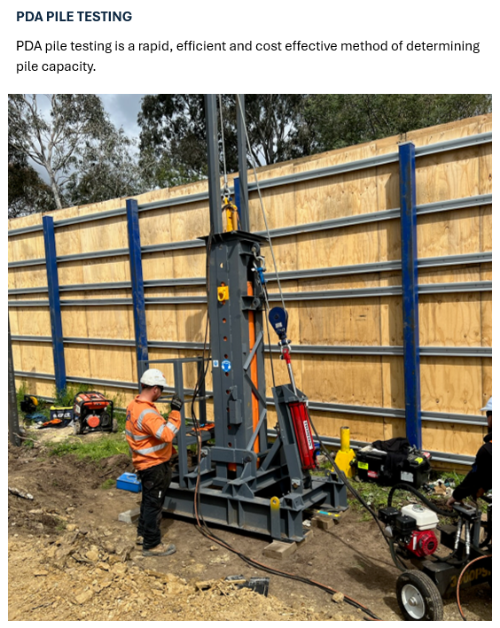
PDA load testing to verify capacity is an important quality control aspect for the system
Grout/concrete testing is performed to verify that the grout / concrete strength reaches the minimum design requirements
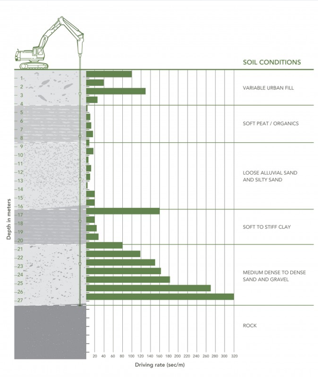
Driving and Driving Rates
Quality control during DIPP installation is largely focused on monitoring pile penetration and penetration rates during driving. Each section of Ductile Iron Pipe Pile is marked in one meter increments to assist with monitoring the length of time required to drive 1 meter of pile into the ground. The rates of penetration are used as indicators of geotechnical resistance and pile capacity. For piles developing capacity in friction, the drive rates provide confirmation that the pile is penetrating into the competent bonding strata. For piles developing the capacity in end-bearing, the drive rates are measured (seconds/mm) to verify the adequate “set” criteria is achieved. Drive rates are monitored for both End-Bearing piles and also Friction Piles.
The figure below shows an illustration of driving rates with depth that is obtained for a pile.
The rate of penetration for Friction Ductile Iron Pipe Piles is used real-time during pile installation to determine the depth at which the bond layer (competent layer in which the bond zone is developed) is encountered. This is based on noting a marked increase in the driving resistance that is consistent with the anticipated depth of the bond layer. The pile is then driven a specified depth into the better layer based on the design requirements.
Depth of Termination
For End-Bearing Piles, the depth of termination is determined based on either refusal on a hard layer (rock) where further penetration or advancement of the pile is not feasible. Alternatively, piles may be terminated when a “set” criteria is met. The “set” criteria is defined as a limited amount of deflection observed while driving the pile for a particular time limit. Decades of installation and verification testing indicate that a “set” criteria of 25mm or less of penetration in 50 seconds or longer is adequate to achieve the design geotechnical capacity for most design cases. Project-specific variations to set criteria are often made and established based on site-specific load testing.
Friction Ductile Iron Pipe Piles are not designed to be installed to a refusal layer or a specific “set” criteria. Instead, the grouted elements are designed to advance a particular depth into a competent strata to develop sufficient bonding length to generate the required design capacity through friction. Early refusal or “set” of a friction pile may still be acceptable for a compression pile depend on the design requirements.
Pile Testing
The results of the PDA load tests are used to verify the design capacity of the Ductile Iron Pile. Many options for load test interpretation are used in the pile industry. Determination of the acceptance requirements need to rely on the project performance specifications or local code interpretation.